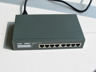
ROUTERS VERSUS SWITCHES

How do you decide if you should purchase a switch or a router? The following section lists the main differences between the two devices. However, switch and router capabilities vary widely. To find out what capabilities a particular product offers, you should contact the vendor:

Some switches may forward packets faster than a router forwards packets.

You do not need multiple network addresses with a switch (if network addresses are precious).

A switched network has one broadcast/multicast domain.

Routers do not broadcast packets. (Some routers allow you to enable broadcast forwarding, but don't do it!)

Some routers offer sophisticated filtering capabilities.

Routers enable you to use two network addresses (if node addresses are limited).

Some routers can act as a firewall.

Some routers can prioritize traffic.


The following technologies enable routers to perform specialized functions to improve information flow and establish a "first defense" against network intruders:

Traffic filtering and firewalling

Traffic prioritization

Traffic grouping

Variety of routing and routed protocols supported


Network Device Part 4: Routers

Whereas switches can only examine and forward packets based on the contents of the MAC header, routers can look further into the packet to discover the network for which a packet is destined. Routers make forwarding decisions based on the packet's network-layer header (such as an IPX header or IP header). These network-layer headers contain source and destination network addresses.

Local devices address packets to the router's MAC address in the MAC header. After receiving the packets, the router must perform the following steps:

1. Check the incoming packet for corruption, and remove the MAC header . The router checks the packet for MAC-layer errors. The router then strips off the MAC header and examines the network-layer header to determine what to do with the packet.

2. Examine the age of the packet. The router must ensure that the packet has not come too far to be forwarded. For example, IPX headers contain a hop count. By default, 15 hops is the maximum number of hops (or routers) that a packet can cross. If a packet has a hop count of 15, the router discards the packet.

IP headers contain a Time to Live (TTL) value. Unlike the IPX hop count, which increments as the packet is forwarded through each router, the IP TTL value decrements as the IP packet is forwarded through each router. If an IP packet has a TTL value of 1, the router discards the packet. A router cannot decrement the TTL value to 1 and then forward the packet.

3. Determine the route to the destination. Routers maintain a routing table that lists available networks, the direction to the desired network (the outgoing interface number), and the distance to those networks. After determining which direction to forward the packet, the router must build a new header. (If you want to read the IP routing tables on a Windows 95/98 workstation, type ROUTE PRINT in the DOS box.)

4. Build the new MAC header and forward the packet. Finally, the router builds a new MAC header for the packet. The MAC header includes the router's MAC address and the final destination's MAC address or the MAC address of the next router in the path.


You should try capturing the packets on each side of a router on your company's network. You will be able to see the change in the hop count or TTL value and the new MAC header. When you analyze a communication, you should examine the network layer to determine the actual source and destination of the packet.

What special feats can routers perform that switches cannot? Because routers operate at layer three of the OSI model, they support forwarding based on network addresses (as opposed to forwarding based on MAC addresses or VLAN designations). Routers can also forward packets based on the best known path (especially in the case of link state routers). In addition, routers can provide detailed filters based on the source and destination network address, as well as the source and destination process (as defined in the port number field in the network header).


Now routers are used to connect networks together and route packets of data from one net- 
work to another. Cisco became the de facto standard of routers because of its high-quality 
router products, great selection, and fantastic service. Routers, by default, break up a broad- 
cast domain—the set of all devices on a network segment that hear all the broadcasts sent on 
that segment.

There are two advantages of using routers in your network: 
     They don’t forward broadcasts by default. 

     They can filter the network based on layer 3 (Network layer) information (e.g., 
     IP address). 

    Four router functions in your network can be listed as follows: 
     Packet switching 

     Packet filtering 

     Internetwork communication 

     Path selection 


Unlike layer 2 switches, which forward or filter  frames, routers (layer 3 switches) use logical addressing and provide what is called packet switching. Routers can also provide packet filtering by using access lists, and when routers connect two or more networks together and use logical addressing (IP or IPv6), this is called an internetwork. Last, routers use a routing table (map of the internetwork) to make path selections and to forward packets to remote networks.

Network Device Part 3: Switches


Bridges usually connect two linear network segments (with one port for each segment). Switches, on the other hand, can connect devices together (with one port for each device). Because most bridges have been replaced by switches, this section focuses on switches.
Switches forward packets based on the destination media access control (MAC) address. Switches learn where devices are located when the devices initially communicate on a network. Switches then put this address information in a table.


When forwarding a packet, switches do not change the packet's contents (such as the network address or the MAC address). In a basic switched environment, all the devices are on the same network.

Like hubs, switches forward all broadcast packets and multicast packets to all ports. After all, these packets are addressed to a group or set of devices.

Switches also forward packets that are addressed to unknown MAC addresses to all active ports. If a MAC address is unknown, switches assume that they have not yet learned about that MAC address. When the intended recipient replies to the packet, switches learn where the MAC address is located.

Switches typically forward packets quickly because they do not make the more complex forwarding decisions that routers make. Although switches are fast, they have do have some inherent disadvantages. For example, consider how a switch would handle the following:

Part of a network is Token Ring, and the other part of the network is Ethernet.

All devices are communicating with one host or port.

A broadcast storm occurs.

A device sends a fragment.

A switched network contains a loop.

Network traffic must be separated into groupings.

A station sends packets to an invalid address.

Unfortunately, these issues can create problems for basic switches. If you must address one of these issues on your company's network, you must purchase a switch with advanced features, such as the following:

Translational switching

Fat pipes

Broadcast throttling

Fragment-free switching

Spanning tree protocol for loop resolution

Virtual LANs (VLANs)


Conversely, switches aren’t used to create internetworks (they do not break up broadcast
domains by default); they’re employed to add functionality to a network LAN. The main
purpose of a switch is to make a LAN work better—to optimize its performance—providing
more bandwidth for the LAN’s users. And switches don’t forward packets to other networks
as routers do. Instead, they only “switch” frames from one port to another within the
switched network.
   By default, switches break up collision domains. This is an Ethernet term used to describe
a network scenario wherein one particular device sends a packet on a network segment, forc-
ing every other device on that same segment to pay attention to it. At the same time, a different
device tries to transmit, leading to a collision, after which both devices must retransmit, one
at a time. Not very efficient! This situation is typically found in a hub environment where each
host segment connects to a hub that represents only one collision domain and only one broad-
cast domain. By contrast, each and every port on a switch represents its own collision domain.


NOTE:

Switches create separate collision domains but a single broadcast domain. 
Routers provide a separate broadcast domain for each interface. 


Network Devices Part 2: Bridges

The term bridging was introduced before routers, switches and hubs were implemented, so 
it’s pretty common to hear people referring to bridges as switches. That’s because bridges and 
switches basically do the same thing—break up collision domains on a LAN


So what this means is that a switch is basically just a multiple-port bridge with more brain-
power, right? Well, pretty much, but there are differences. Switches do provide this function,
but they do so with greatly enhanced management ability and features. Plus, most of the time,
bridges only had 2 or 4 ports. Yes, you could get your hands on a bridge with up to 16 ports,
but that’s nothing compared to the hundreds available on some switches!


You would use a bridge in a network to reduce collisions within broadcast 
                   domains and to increase the number of collision domains in your network. 
                   Doing this provides more bandwidth for users. And keep in mind that using 
                   hubs in your network can contribute to congestion on your Ethernet network. 
                   As always, plan your network design carefully! 

Network Devices Part 1:HUB


Hubs, simple multistation access units, and repeaters are the most basic forwarding devices. These devices aren't very intelligent. In fact, they don't know what a packet is; they see only 1s and 0s. Essentially, these devices forward bits from one port to another. For example, a hub receives a 1 bit in one port and copies this 1 bit to all other ports.

Of course, handling packets in this way can create problems if a device sends a broadcast storm. In this case, the broadcast storm affects all of the devices that are connected to the hub. A switch that offers broadcast throttling capabilities or a router may help you better control network traffic. These more advanced products work at the second layer in the OSI mode.


Hub never break...

Collision Domin  (Discus Earlier) and

Broadcast Domain (Discus Earlier)

CCNA Associate Course - 640-802 Overview

CCNA Associate Course - 640-802 Overview 


·         Introduction
·         Network Devices & Components
·         OSI Model & TCP/IP Model
·         Network Applications
·         Connecting to the IOS Command Line Interface
·         Cisco IOS PING, Traceroute, & TFTP
·         IOS File & Configuration Management with TFTP
·         TFTP Servers & Network Management Systems (NMS)
·         Local Area Networks (LANs) Overview
·         IP ARP, MAC Address Flooding & Learning
·         Collision Domains, Broadcast Domains, & VLANs
·         Cisco Discovery Protocol (CDP)
·         VLAN Trunking & VTP
·         Spanning-Tree Protocol (STP)
·         STP Path Selection & RSTP
·         IP Addressing, Subnetting, & VLSM
·         IP Routing
·         Inter-VLAN Routing & Static Routing
·         Static vs. Dynamic Routing
·         Dynamic Routing Configuration
·         RIPv2 Overview & Configuration
·         EIGRP Overview
·         EIGRP Configuration
·         OSPF Overview
·         OSPF Configuration Part 1
·         OSPF Configuration Part 2
·         IPv6
·         Cisco Security Device Manager (SDM)
·         Dynamic Host Configuration Protocol (DHCP)
·         Domain Name System (DNS)
·         Network Address Translation (NAT)
·         Access Control Lists (ACLs)
·         Wide Area Network (WAN) Overview
·         Point-to-Point Protocol (PPP)
·         Frame-Relay Overview
·         Frame-Relay Configuration


I am going cover all above write topic step by step in my upcoming post.
Powered by Blogger